Language
High voltage switchgear is the integrated assembly of circuit breakers, isolators, and relays that control and protect power systems above 36 kV. It detects faults and interrupts high currents to guarantee safety and service continuity. Options include air-, gas-, oil-, and vacuum-insulated designs, selected by footprint, maintenance, and dielectric performance. Standards like IEC 62271 and IEEE C37 guide ratings and testing. Modern systems add sensors for condition monitoring and automation. Explore types, components, applications, and how to choose the right solution.
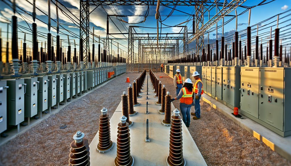
High-voltage switchgear is an integrated assembly of switching and protection devices—such as circuit breakers, disconnectors, fuses, relays, and instrument transformers—engineered for power networks operating above 36 kV.
Integrated high-voltage switchgear powering networks above 36 kV with precise switching, protection, and measurement components.
In an hv switchgear overview, it is defined by its ability to control, protect, and isolate high-energy circuits with precision. It detects abnormal conditions, interrupts fault currents, and enables safe maintenance through reliable isolation and earthing.
High voltage switchgear also facilitates accurate metering and automation, supporting selective coordination and system resilience. Architectures range from air-insulated to compact gas-insulated configurations, selected by environment, footprint, and operational risk.
Operators value its deterministic performance, remote operability, and compliance with rigorous standards. Proper specification, installation, and trained operation guarantee predictable behavior, minimized downtime, and scalable grid integration.
Why do engineers segment switchgear into LV, MV, and HV? Because voltage class dictates insulation strategy, arc energy, protection speed, and installation constraints—directly impacting risk, footprint, and lifecycle cost.
LV typically spans kV, MV >1 kV to ~36 kV, and HV >36 kV. Selection aligns with load density, network topology, and operational philosophy. An HV switchgear manufacturer will emphasize reliability, condition monitoring, and interoperability across classes, plus an AIS vs GIS switchgear comparison for space and environment control.
High-voltage switchgear spans several insulation approaches—air-insulated (AIS), gas-insulated (GIS), oil-insulated, vacuum-insulated, and hybrid GIS-AIS configurations.
Each option balances footprint, dielectric strength, maintenance needs, environmental impact, and lifecycle cost.
The following overview outlines where each type excels and how to align selection with site constraints and performance objectives.
Air-insulated switchgear (AIS) employs ambient air as the primary insulating medium, making it a cost-effective and straightforward choice for high-voltage installations above 36 kV.
As outdoor-oriented equipment, air insulated switchgear (ais) offers open layouts, easy visual inspection, and straightforward maintenance. It aligns with hv switchgear safety standards through defined clearances, robust interlocking, and dependable earthing.
Utilities select AIS where space is available, lifecycle transparency matters, and expandability is required without complex enclosures.
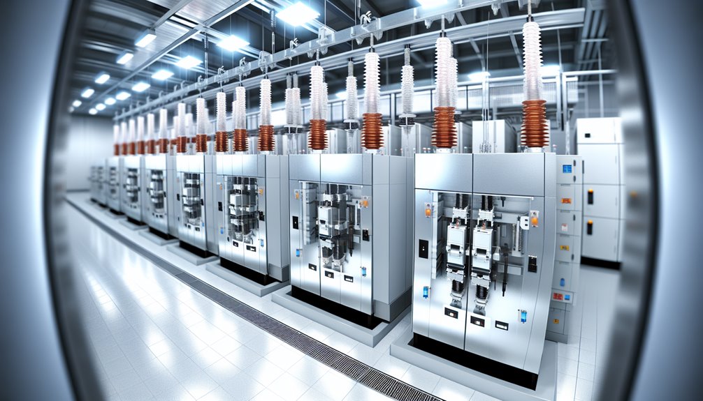
Where AIS favors open layouts and physical clearances, gas-insulated switchgear (GIS) achieves compactness by enclosing conductors and interrupting devices within sealed metal compartments filled with SF6 or alternative gases. This architecture delivers high dielectric strength, arc containment, and minimal footprint, enabling indoor siting in space-constrained substations and harsh environments. Modular bays support ring, double-bus, and breaker-and-a-half schemes with high reliability.
Operators value gas insulated switchgear (GIS) for low maintenance, corrosion resistance, and reduced outage exposure. Asset control hinges on condition monitoring of gas density, partial discharge, contact wear, and interlock integrity. Commissioning and lifecycle assurance follow HV switchgear testing procedures: insulation resistance, power-frequency withstand, very low frequency (VLF) or equivalent, contact timing, secondary injection of protection relays, interlock verification, and tightness tests for gas compartments.
Oil-insulated switchgear (OIS) employs mineral or synthetic insulating oil to provide high dielectric strength, arc quenching, and thermal dissipation within sealed enclosures. It serves transmission and subtransmission nodes where robustness, overload endurance, and proven arc energy management are prioritized.
Designs range from bulk oil circuit breakers to minimal-oil compartments integrating relays, disconnects, and bushings with instrumentation.
1) Advantages: high impulse withstand, strong arc quenching for severe duty cycles, and thermal headroom that stabilizes components, extending hv switchgear lifespan when oil quality is maintained.
2) Risks: flammability, oil leaks, and environmental handling obligations increasing maintenance cost and compliance requirements.
3) Controls: dissolved gas analysis, moisture limits, and dielectric testing sustain reliable oil insulated switchgear performance.
4) Modernization: ester fluids, sealed tanks, online sensors, and retrofit interrupters reduce footprint, losses, and lifecycle risk.
Vacuum-insulated switchgear (VIS) employs sealed vacuum interrupters as the primary dielectric and arc-quenching medium, delivering high interrupting capability with minimal contact erosion and no insulating gas or oil. It offers compact footprints, rapid dielectric recovery, and low maintenance, making it attractive for mv-to-hv switchgear for power plants and industrial campuses seeking measurable control over lifecycle cost and reliability. Compared with air insulated switchgear (AIS), VIS reduces space, contamination risk, and service intervals while avoiding SF6.
| Attribute | VIS (Value / Impact / Strength) | Control Implication |
|---|---|---|
| Compactness | High | Enables smaller switch rooms and higher power density per square meter. |
| Maintenance | Low | Predictable OPEX and reduced downtime for service. |
| Arc Performance | Excellent | Faster fault clearing and lower mechanical and thermal stress on connected equipment. |
| Reliability | High | Improves network stability and reduces unplanned outages. |
| Safety | Enhanced | Arc-proof enclosures and advanced interlocking protect operators. |
| Customization | Flexible | Configurable busbar schemes, modular panels, and protection settings for diverse project needs. |
| Automation Ready | Yes | Integrates easily with SCADA and digital monitoring for smarter grid control. |
Designers select vacuum interrupter ratings by short-circuit duty, mechanical endurance, and insulation coordination. Metal-clad or metal-enclosed forms integrate relays, interlocks, and remote operation for disciplined switching authority.
Hybrid or mixed GIS-AIS switchgear combines gas-insulated modules for compact, high-dielectric functions with air-insulated sections for accessible switching, metering, or bus extensions.
This architecture optimizes footprint, cost, and maintainability while preserving protection, control, and reliability at transmission and sub-transmission levels.
Utilities deploy hybrid yards to retrofit aging AIS, expand capacity without full rebuilds, or phase-in GIS where space or environmental constraints exist.
Interface modules manage changes between pressurized GIS busbars and open-air conductors, ensuring dielectric coordination and maintainable clearances.
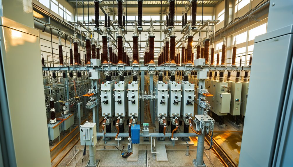
The backbone of HV switchgear comprises circuit breakers for fault interruption, disconnecting switches (isolators) for visible isolation, and earthing switches to guarantee de-energized equipment is safely grounded.
Current transformers (CTs) and voltage transformers (VTs/PTs) provide accurate measurements and inputs for protection, control, and metering.
Together, these components enable selective protection, safe maintenance, and data-driven operation of high-voltage networks.
Heart of protection and control, circuit breakers in high-voltage switchgear interrupt fault currents to safeguard equipment and personnel while maintaining system stability. They sense abnormal conditions via protective relays and open contacts to extinguish arcs and clear faults, preserving service to healthy sections.
Selection aligns with system voltage, short-circuit duty, insulation medium, and operating philosophy.
Often regarded as the gatekeepers of safe work boundaries, disconnecting switches—or isolators—provide visible, load-free separation of high-voltage circuits to ensure the safety of both personnel and equipment.
Unlike circuit breakers (SF₆, vacuum, or oil types), isolators do not interrupt fault current. Their role is to establish a verifiable air gap so downstream assets can be serviced under documented, de-energized conditions.
Typical designs include single- and double-break configurations with center- or side-rotating blades, available in manual or motorized operation. Selection depends on insulation type (AIS or GIS), creepage distance, voltage withstand rating, and interlocking logic with associated breakers and control systems.
| Objective | Control Lever / Design Feature |
|---|---|
| Isolation Certainty | Visible air gap, mechanical and key interlocks |
| Operability | Motorized drives, local/remote position indication |
| Reliability | Corrosion-resistant contacts, robust hinge assemblies, maintenance access |
Forward-looking systems now integrate position sensors, condition monitoring, and remote permissive logic within SCADA environments to minimize human error and enhance switching safety.
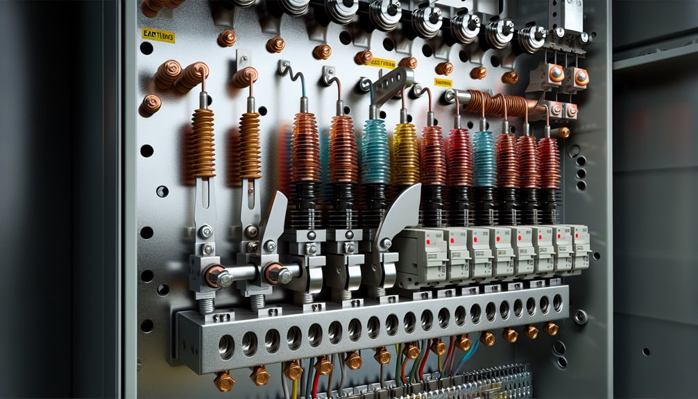
During maintenance or fault conditions, earthing switches provide a deliberate, low‑impedance path to ground that safely discharges trapped charge and induced or fault currents in high‑voltage circuits. They complement isolators by ensuring de‑energized sections are not only separated but proven dead and bonded to earth, enabling controlled, worker‑safe access.
Designs range from fast‑acting make‑proof types to high‑speed earthing in GIS, with clear position indication and interlocking to prevent misoperation.
1) Functions: establish a visible, verifiable earth; dissipate residual energy; control induced voltages; and enable safe test points.
2) Selection: rated short‑time current, peak withstand, making capacity, mechanical endurance, and environmental sealing.
3) Integration: electrical and key interlocks, SCADA indication, padlocking, and live‑line detection.
4) Maintenance: inspect contacts, linkages, and earthing conductors; verify continuity; test operating mechanisms.
Current transformers (CTs) in high-voltage switchgear scale primary currents to standardized secondary values—typically 1 A or 5 A—enabling accurate metering and fast, selective protection without exposing instruments or relays to primary fault energy.
They provide galvanic isolation and a proportional replica of primary current, allowing protection relays to detect overloads, short circuits, and asymmetries with high fidelity. Accuracy classes and burden matching are selected to maintain ratio and phase precision across expected fault ranges, preventing relay misoperation.
CT cores and windings are engineered for thermal withstand and dynamic stability during high fault currents.
Correct polarity, saturation margin, and knee-point specification underpin dependable differential, overcurrent, and distance schemes.
Strategic placement on each phase and neutral ensures thorough coverage, while test blocks and shorting links support safe maintenance and commissioning.
Voltage transformers (VTs or PTs) in high-voltage switchgear step primary voltages down to standardized secondary levels—commonly 100 V or 110 V—providing accurate measurement, protection inputs, and galvanic isolation between the HV network and control systems.
They enable precise metering, relay functions, and safe interfacing with automation without exposing low-voltage equipment to transmission-level potentials. Designs include electromagnetic VTs and capacitive voltage transformers (CVTs) for EHV lines, selected by accuracy class, burden, and insulation requirements.
1) Measurement integrity: High accuracy classes support revenue metering and power quality analytics under varying loads.
2) Protection reliability: Stable voltage inputs drive distance, over/under-voltage, and synchronism-check elements.
3) Safety and isolation: Robust dielectric barriers prevent hazardous transfer to control circuits.
4) Deployability: Options for AIS/GIS, grounded-neutral schemes, and redundancy elevate availability and control.
Sentinels against transients, surge arresters safeguard high-voltage switchgear by clamping lightning- and switching-induced overvoltages to safe levels and diverting surge energy to ground. They protect insulation, circuit breakers, instrument transformers, and control wiring from dielectric stress and thermal damage, preserving system availability.
Modern metal-oxide varistor (MOV) arresters exhibit high nonlinearity: very high impedance at system voltage, very low impedance during surges. Correct selection considers maximum continuous operating voltage (MCOV), temporary overvoltage (TOV) withstand, energy rating, discharge class, and coordination with insulation levels (BIL/BSL).
Strategic placement at incoming lines, transformer terminals, and critical interfaces minimizes surge propagation.
Maintenance focuses on visual inspection, leakage current trending, and environmental sealing integrity. Digital monitoring enables predictive replacement and fleet-wide analytics.
Proper earthing and lead length control guarantee low inductance discharge paths and repeatable protection performance.
Backbones of power flow, busbars are robust conductive bars that form the primary current paths within high-voltage switchgear, interconnecting incoming feeders, outgoing circuits, and tie sections. They consolidate fault duty, enable sectionalization, and support reliable load transfer.
Materials and cross-sections are selected to manage thermal rise, magnetic forces, and short-circuit stresses while maintaining dielectric clearances to adjacent phases and earth. Configurations (single, double, ring) determine flexibility, redundancy, and maintenance access without compromising service continuity.
While busbars carry and consolidate current within the gear, the enclosure defines the boundary that keeps that energy controlled, safe, and reliable. It provides mechanical protection against impact, ingress, and contamination, preserving clearances and creepage distances that uphold insulation integrity at high voltage.
Robust housings—air- or gas-insulated—seal internal components from moisture, dust, corrosives, and wildlife, stabilizing dielectric performance and extending service life.
Engineered for predictable behavior under internal faults, enclosures contain pressure, direct venting, and minimize propagation of damage to adjacent bays. Materials and construction target defined ingress protection, corrosion resistance, seismic strength, and thermal management to maintain ratings.
Modular designs support maintainable compartments and safe access points. Forward-looking designs integrate eco-efficient materials, compact footprints, and condition-readiness to sustain reliability across evolving network demands.
Protection relays form the intelligence layer of high-voltage switchgear, continuously monitoring currents, voltages, frequency, and sequence to detect overloads, short circuits, and earth faults with defined selectivity and speed.
They interpret measurements from instrument transformers and, upon detecting abnormal conditions, issue deterministic trip commands to circuit breakers to isolate only the faulty section, preserving system stability and availability.
Settings are engineered to coordinate with upstream and downstream devices, ensuring time–current discrimination and dependable clearing.
1) Core functions: anomaly detection, logic decision, trip signaling, and post-fault indication for targeted isolation and rapid service restoration.
2) Key types: overcurrent, earth-fault, distance, differential, and frequency relays tailored to network topology.
3) Performance metrics: sensitivity, security, dependability, speed, and availability.
4) Future-ready features: IEC 61850 interoperability, synchrophasor-assisted logic, cybersecurity hardening, and data-driven maintenance analytics.
Control panels serve as the command interface of high-voltage switchgear, consolidating operating switches, meters, and protective relays into a centralized, ergonomic hub for monitoring and control. They structure operator actions into clear, authoritative pathways: select, verify, execute.
Human-machine interfaces present status, alarms, and trend data with disciplined hierarchy, while interlocks enforce safe sequences and prevent inadvertent operations. Integration with instrument transformers yields accurate metering; logic schemes coordinate permissives, transfer controls, and remote commands via SCADA or IEC 61850 architectures.
Design emphasizes segregation of control power, clear labeling, and arc-resistant enclosures where required. Modular layouts support rapid replacement and firmware updates.
Diagnostic pages expose relay health, time synchronization, and event records. Forward-looking panels adopt cybersecurity hardening, analytics-ready data models, and engineered workflows that accelerate decisive, compliant action.
From the operator-focused control panel, command intent meets automated fault clearing through fault interrupters. In high-voltage switchgear, these devices detect abnormal current, open rapidly to interrupt the arc, and segment the network so healthy feeders remain energized.
Their mission is speed, selectivity, and minimal service disruption—operating automatically to clear faults and restore service quickly in distribution networks. Coordination with protection relays, instrument transformers, and isolation devices guarantees targeted operation and safe re-energization after verification.
1) Core functions: sense fault magnitude/direction, interrupt within cycles, and confine disturbance to the smallest zone.
2) Performance priorities: high interrupting rating, arc-quenching efficiency, mechanical endurance, and reclosing logic suited to system policy.
3) Integration: seamless with AIS or GIS layouts and digital monitoring.
4) Reliability: preventive testing, contact wear assessment, and firmware validation.
Few components in high-voltage assemblies bridge control logic and power flow as directly as contactors. In HV switchgear, contactors execute rapid, repeatable making and breaking of load currents under precise command signals, coordinating with relays and control panels to enforce operating intent.
Arc-control mechanisms, robust contact geometry, and reliable coil actuation enable high endurance and minimal bounce, preserving equipment life and power quality.
Engineered for automation, they operate automatically to clear faults and restore service quickly in distribution networks when paired with protective logic and interlocks.
Typical features include auxiliary contacts for status feedback, mechanical and electrical interlocks for selectivity, and coil suppression for control stability.
In digitalized architectures, contactors integrate with condition monitoring, enabling predictive maintenance, deterministic sequencing, and faster, safer re-energization strategies.
Fuses in high-voltage switchgear provide fast, deterministic overcurrent protection by sacrificing a calibrated fusible element to interrupt fault energy before equipment is damaged. Their value lies in precise time-current characteristics, inherent selectivity, and passive reliability.
Properly rated HV fuses limit let-through energy, curtailing thermal and mechanical stress on transformers, feeders, and auxiliary circuits. Integration with disconnects and relays supports coordinated protection schemes across complex networks while maintaining operational control.
1) Specify ratings with margin: system voltage, prospective fault current, I2t let-through, and permissible peak current to guarantee interruption without overstress.
2) Coordinate with upstream breakers and downstream device withstands to achieve selective isolation.
3) Verify installation clearances and insulation class for AIS or GIS applications.
4) Maintain via visual inspection, resistance checks, and replacement after any operation; never re-energize on a questionable element.
The earthing grid forms a buried network of interconnected conductors designed to establish a low-impedance path to ground, stabilizing system reference voltage and ensuring personnel safety.
In high-voltage switchyards, it equalizes surface potential during faults, limits touch and step voltages, and provides a reliable return path for fault current.
Design priorities include mesh geometry, conductor sizing, and soil resistivity management to achieve the required impedance, current-carrying capacity, and thermal margins. Grid performance is verified through continuity and resistance testing, with periodic inspections to detect corrosion or soil movement that could compromise system integrity.
| Element | Purpose | Control Metric |
|---|---|---|
| Mesh Layout | Potential equalization | Maximum grid impedance (Ω) |
| Conductors / Ground Rods | Fault current dissipation | Thermal ampacity margin |
| Bonds / Connections | Long-term reliability under stress | Measured resistance continuity |
Proper integration bonds all switchgear enclosures, neutral points, metallic structures, and equipment frames to the grid, ensuring predictable protection settings, arc-flash risk reduction, and consistent fault clearing behavior under real operating conditions.
Step-up and step-down transformers in high-voltage switchgear enable precise voltage transformation between generation, transmission, and distribution levels, optimizing efficiency and equipment compatibility.
In substations, step-up units elevate generator output to transmission voltages to minimize I²R losses, while step-down units reduce transmission voltages to safe, usable levels for distribution and end-use equipment.
Integrated with protective relays and instrument transformers, they support selective coordination and fault isolation without compromising service continuity.
1) Step-up: raises generator voltages for long-distance transmission, reducing current and conductor size.
2) Step-down: delivers appropriate service voltages to feeders, MCCs, and critical loads.
3) Control: on-load tap changers fine-tune voltage under varying demand and renewable intermittency.
4) Reliability: monitoring of oil, bushings, PD, and thermal profiles informs condition-based maintenance and risk-driven outage planning.
In a high-voltage switchgear system, normal operation enables controlled power flow, while instrument transformers, sensors, and protection relays continuously monitor voltage, current, and frequency.
Under healthy conditions, circuit breakers remain closed, maintaining continuity of supply, while disconnectors establish visible isolation boundaries for safe maintenance.
When a disturbance or fault occurs, protective relays compare real-time measurements with preset thresholds to identify abnormal conditions. Upon detection, they issue a trip command with precise selectivity and time coordination.
The circuit breaker then interrupts the fault current through rapid arc quenching using media such as SF₆ gas, vacuum, or oil, isolating the faulted section within milliseconds.
Earthing switches secure the de-energized portion, ensuring operator safety during subsequent work.
Proper coordination ensures upstream and downstream protection devices operate in sequence, preserving supply to unaffected feeders.
System redundancy, breaker-fail protection schemes, and alternative supply paths improve operational reliability and availability.
After fault clearance and verification, controlled re-energization restores normal service to the network.
Although high-voltage switchgear technologies vary by application and region, compliance is anchored to internationally recognized standards that define design, testing, safety, and environmental performance.
Core frameworks include IEC 62271 for high-voltage switchgear assemblies, ANSI/IEEE C37 and IEEE C37.100 series for North American practices, and GB/T for Chinese conformity. These standards specify dielectric ratings, short-circuit performance, mechanical endurance, protection coordination, and routine/type tests.
Buyers seeking control should require documented conformity and traceable test evidence.
Environmental and safety obligations include SF6 lifecycle management under IEC 60376 (new gas specifications) and applicable EU F-gas Regulation for leak limits, handling, and reporting.
1) Verify certificates, type-test reports, and factory routine tests.
2) Confirm insulation coordination and short-circuit ratings.
3) Audit SF6 handling, leak detection, and recovery.
4) Guarantee manufacturer quality systems and witnessing.
A rigorous cost and total ownership analysis of high‑voltage switchgear weighs upfront expenditure against decades-long operational impacts. Capital outlay spans equipment, installation, civil works, transportation, and commissioning. Price is shaped by voltage class, insulation type, customization, and local regulations.
AIS typically offers lower purchase and civil costs but requires larger footprints; GIS commands higher equipment and commissioning costs yet reduces land use and can lower site works.
Lifecycle economics hinge on maintenance cadence and outage risk. AIS maintenance is more frequent and space‑dependent; GIS maintenance is less frequent but specialized.
Over 30 years, GIS can offset premiums via reduced losses, higher availability, and compact layouts. As a benchmark, 132 kV GIS often exceeds comparable 145 kV AIS, but site constraints can reverse total ownership advantage.
Selecting a high-voltage switchgear partner is a long-term decision that defines your system’s reliability, compliance, and total cost of ownership. Beyond upfront pricing, buyers should evaluate engineering capability, delivery performance, and lifecycle transparency across decades of operation.
A trusted HV switchgear manufacturer must demonstrate verifiable expertise in AIS/GIS configurations, digital protection and monitoring, and eco-efficient solutions for voltages above 36 kV — all tailored to project and site conditions.
Cybersecure, interoperable controls and a stable supply chain minimize project risk and prevent vendor lock-in.
Key evaluation points:
Contracts should formalize performance guarantees, service response times, and change-control protocols to safeguard investment integrity.
At Conya, we combine engineering precision with manufacturing excellence to deliver high-voltage switchgear solutions built for demanding power networks. From air-insulated and gas-insulated systems to intelligent digital switchgear, Conya is a trusted partner for utilities and industrial customers seeking reliable, safe, and future-ready power distribution.
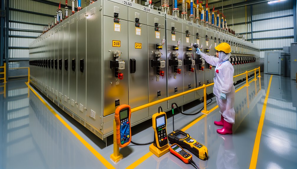
Effective high‑voltage switchgear programs start with disciplined installation best practices, followed by rigorous pre-commissioning testing to verify insulation integrity, protection settings, and control logic.
Sustained reliability depends on risk-based maintenance strategies that combine condition monitoring, scheduled inspections, and calibrated interventions.
Common faults—such as partial discharge, contact wear, CT/PT errors, or control wiring defects—are addressed through structured troubleshooting that uses diagnostics, root-cause analysis, and documented corrective actions.
Although project goals vary, installation best practices for high‑voltage switchgear start with disciplined site preparation and safety-first planning.
A stable, vibration‑controlled foundation guarantees alignment, minimizes mechanical stress, and preserves dielectric performance.
Maintain code‑compliant clearances between phases and to ground to control electric fields, prevent flashover, and enable safe operation.
In indoor rooms, control humidity and temperature to protect insulation systems, prevent condensation, and sustain relay and sensor accuracy.
Establish safe access zones for operators and maintain egress routes.
Cable terminations require verified lug torque, bending radii, and sealing to exclude moisture and contaminants.
Always align procedures with IEC 62271 or IEEE C37.
1) Engineer foundations and seismic anchorage.
2) Enforce electrical clearances and barriers.
3) Condition room environment.
4) Verify terminations, seals, and access control.
Validate before energizing. Each high-voltage switchgear lineup undergoes a disciplined pre-commissioning test plan that confirms design intent and operational safety.
Dielectric tests verify insulation strength to earth and between phases, using applied voltage levels per standards. Insulation resistance testing with a calibrated megger confirms absence of leakage paths and moisture.
Contact resistance tests on circuit breaker main contacts guarantee minimal I²R loss and reliable fault clearing.
For GIS or SF6-insulated equipment, an SF6 leakage test verifies gas tightness and records baseline density/pressure.
Functional testing proves all interlocks, tripping and closing circuits, protection relays, and control logic, including fail-safe behavior.
Results are documented with traceable instruments, environmental conditions, and acceptance criteria. Any deviation triggers corrective action and re-test.
Only then is the system released for energization.
When planned from installation through lifecycle testing, maintenance strategies for high‑voltage switchgear minimize downtime and preserve asset integrity. A disciplined program aligns preventive and corrective actions with environmental conditions and duty cycles. Proper maintenance reduces outages and extends equipment life, while records enable trend analysis and risk-based scheduling.
Despite robust design, high-voltage switchgear exhibits recurring faults that trace to insulation stress, thermal issues, and mechanical degradation—especially during installation, acceptance testing, and routine maintenance.
Control-focused teams prioritize early detection: partial discharge indicates insulation deterioration; deploy PD detectors during commissioning and outages.
Overheating signals loose connections or overload; thermography and torque checks verify integrity. Insulation breakdown often follows moisture ingress or aging; perform dielectric tests, replace cracked insulators, and clean/dry contaminated surfaces.
Mechanical symptoms include sticking breaker mechanisms, damaged or misadjusted shutters (not opening/closing), or seized locks; correct with lubrication, alignment, or replacement.
Internal noise arises from partition screws or cable-to-gland contact; tighten, seal, and dress cables.
Electrical anomalies include overheated connectors (retorque, observe nameplate current, replace busbar), control unit maloperation (secure terminals, reseat plugs), and light extinction (replace bulbs, fuses/resistors; clean auxiliary contacts; verify MCCB terminals).
Across diverse sectors, high voltage switchgear enables safe, reliable transmission and distribution by controlling, protecting, and isolating circuits above 36 kV. It underpins grid stability, asset longevity, and personnel safety where power density and continuity are non-negotiable.
Selection between AIS and GIS, protection schemes, and redundancy levels is tailored to risk, footprint, and environmental constraints.
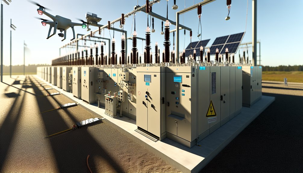
Amid accelerating electrification and urbanization, future high-voltage switchgear is converging on three themes: decarbonization, digitalization, and densification.
SF6-free technologies—green gas alternatives and vacuum GIS—are advancing to meet regulatory pressure while preserving arc-quenching performance and footprint. Digital and smart switchgear embeds IoT sensors, secure edge analytics, and predictive maintenance to reduce outages and optimize asset life, with remote control enabling faster, safer switching.
Modular, compact architectures support urban substations and brownfield retrofits, shortening installation windows and improving scalability.
Market momentum is strong: by 2027, global switchgear is projected at $120.1 billion, with APAC driving capacity additions, Europe prioritizing eco-efficiency, and MENA expanding transmission backbones.
Stakeholders seeking cost control will deploy eco-efficient HV platforms for smart energy management, maximizing availability and energy efficiency.
It reduces remote tampering and ransomware by enforcing network segmentation, MFA, signed firmware, least‑privilege RBAC, secure protocols, continuous monitoring, anomaly detection, immutable logging, offline backups, patch management, application whitelisting, incident playbooks, and tested recovery, preserving deterministic control and availability.
Begin with inventory and de-energization; segregate metals, plastics, and e-waste; recover SF6 and oils via certified handlers; sanitize data; document chain-of-custody; prioritize OEM take-back, reuse, and material recycling; comply with WEEE/IEC/OSHA; verify recyclers; audit outcomes; iterate improvements.
Ambient altitude reduces dielectric strength and cooling, prompting derating of voltage withstand and current/temperature limits. Pollution raises surface leakage and tracking risk, necessitating higher creepage distances, better insulation, and sealing. Engineers apply IEC/IEEE correction factors, enhanced ventilation, and contamination-resistant designs.
Yes—many installations can be retrofitted. Yet the decisive factors emerge: available space, relay compatibility, incident energy studies, and standards. Options include arc-flash relays, maintenance switches, fast earthing switches, zone-selective interlocking, and remote racking—validated by commissioning tests and procedural rigor.
Operators require formal electrical safety training, arc-flash and switching procedures, lockout/tagout, first-aid/CPR, and rescue. Certifications typically include NFPA 70E/IOSH-equivalents, utility or manufacturer qualifications, competency on specific equipment, periodic refreshers, documented switching authority, and evidence of authorized person status with supervised sign-off.
High-voltage switchgear stands at the heart of every reliable power network — ensuring safe operation, precise control, and uninterrupted energy flow. From fault isolation to performance monitoring, each component plays a vital role in sustaining grid stability and protecting critical assets.
At Conya, we bring proven engineering expertise and manufacturing precision to every high-voltage solution we deliver. Our HV switchgear systems are designed for long-term reliability, intelligent protection, and easy integration with your power infrastructure — whether for utilities, substations, or industrial distribution networks.
Partner with Conya to build safer, smarter, and more efficient electrical systems.
👉 Contact our team today to discuss your HV switchgear requirements or request a tailored technical solution.